Multispectrum: A DIY Light Source
There is an ongoing debate in the film scanning community about the best illumination strategy. Narrow-band RGB LEDs offer precise spectral separation of film dye layers. Broadband white light provides spectral flexibility, particularly valuable for aged or degraded stock. A growing number of professional and startup scanners are exploring multispectral approaches — illuminating with several discrete wavelengths and treating each as a separate capture. All three camps have merit, and all three involve real trade-offs.
Tingopix's philosophy has always been to deliver archival-quality results at a fraction of the cost of professional systems, trading budget for speed where necessary. Rather than committing to one illumination paradigm, the goal is to support all of them. This new light source is the hardware that makes that possible.
The Problem: Eight LED Types, One Light Source
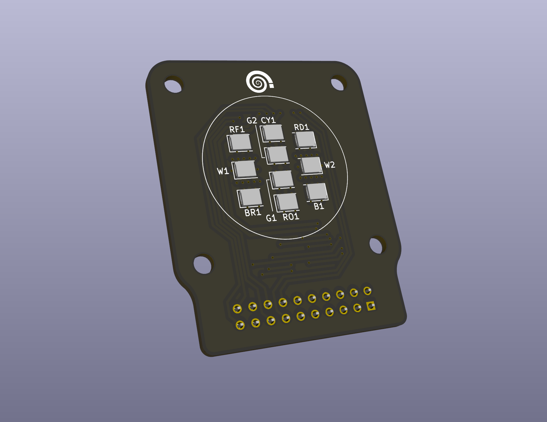
The chosen palette covers eight LED types: one broadband white and seven narrow-band types spanning the spectrum from blue to red. Each of the four LED PCBs carries ten LEDs — two white, two green, and one of each remaining narrow-band type. Electrically, these LEDs share almost nothing: forward voltages and light output vary considerably across the palette. Running them all at a common maximum current requires a driving strategy that can accommodate those differences.
The solution is a series string topology that lessens those differences. White LEDs, with their higher forward voltage, run as four independent strings of two — each driven by its own current mirror transistor. Green LEDs run as two strings of four in series, again each with its own transistor. The remaining narrow-band types each run as a single string. Every string operates at the same maximum current of ~100mA; it is the series configuration that adapts to each LED type's voltage. Where multiple strings exist for the same LED type, the current mirror architecture ensures every string is driven at exactly the same current.
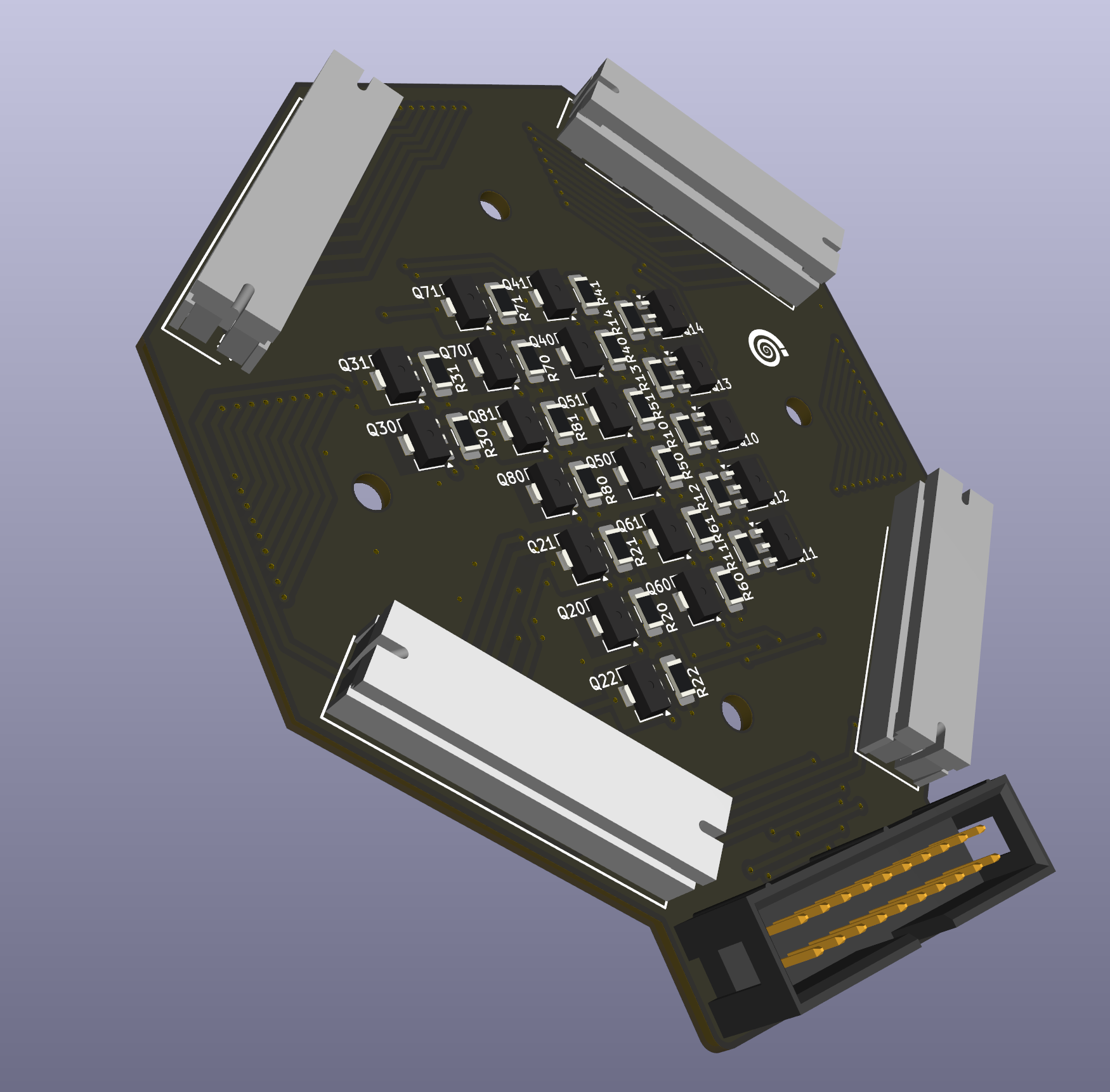
The Wiring Architecture: Drivers at the Back
The current mirror driver board lives at the back of the sphere, not on the LED PCBs themselves. Each of the four LED PCBs connects to the driver board via its own ribbon cable, with individual conductors per LED — allowing the series string arrangements to be resolved at the driver's PCB.
The signal chain flows in one direction: DAC board → driver board → LED PCBs, connected by ribbon cables. At the head of the chain, a 16-bit I2C DAC provides eight independent reference channels, each with its own amplifier for gain and offset adjustment.
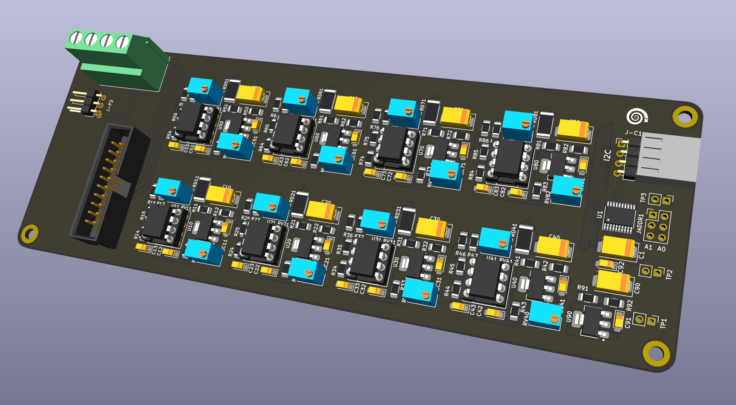
This is where the system's dynamic range lives — each spectral source is continuously and independently variable from a whisper to full output, with the fine resolution of a 16-bit reference. The driver board's current mirrors translate each reference into a stable drive current for its LED strings, and four ribbon cables fan out from there to the LED PCBs.
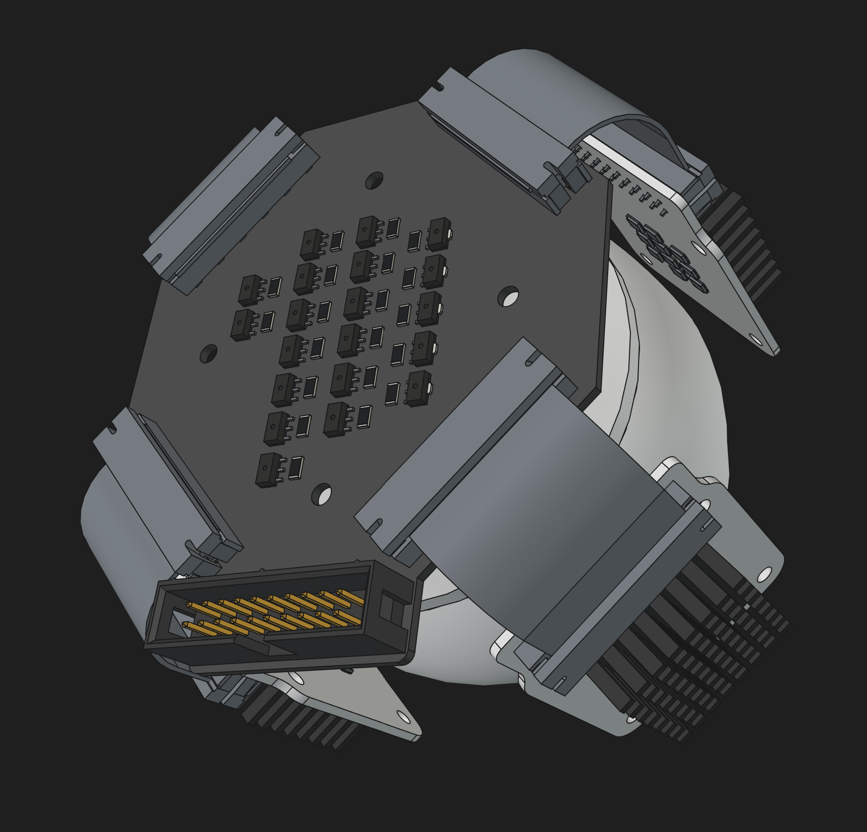
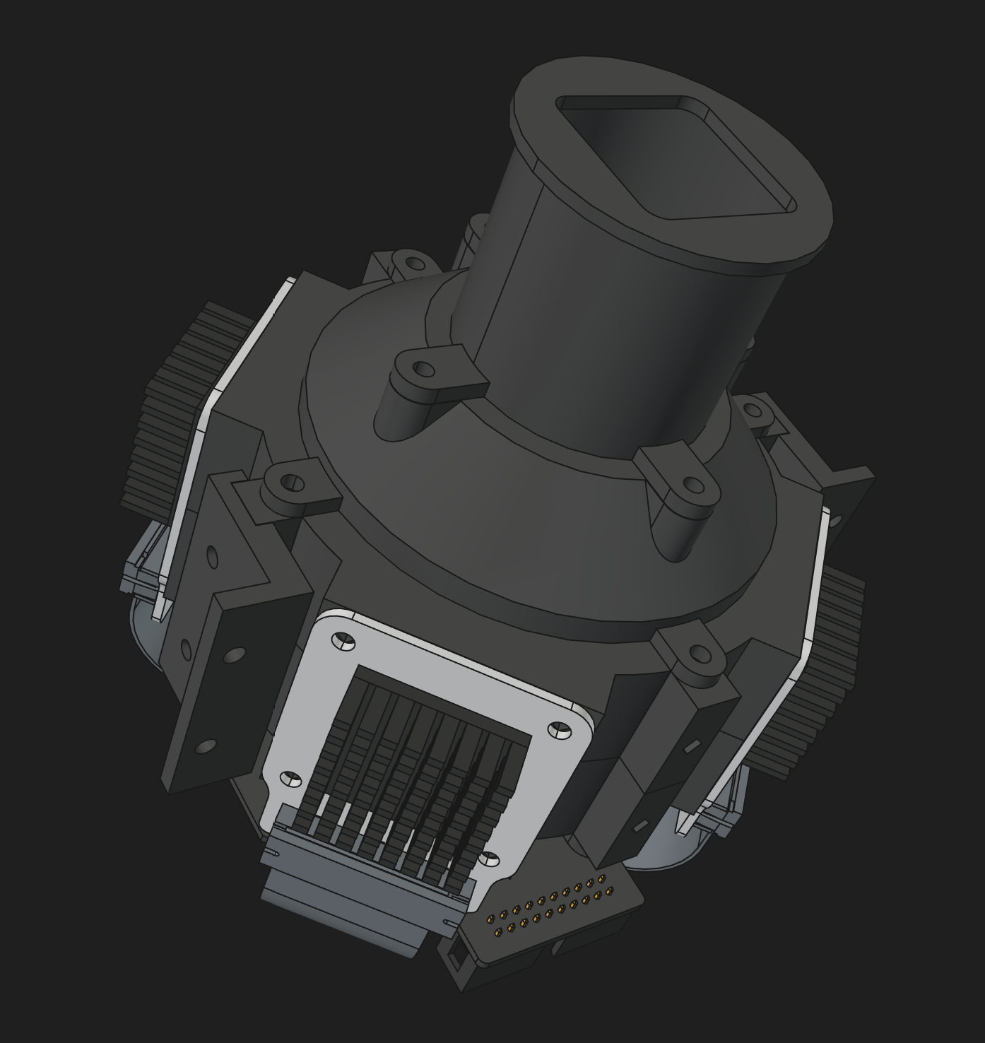
Putting It Together: The Sphere
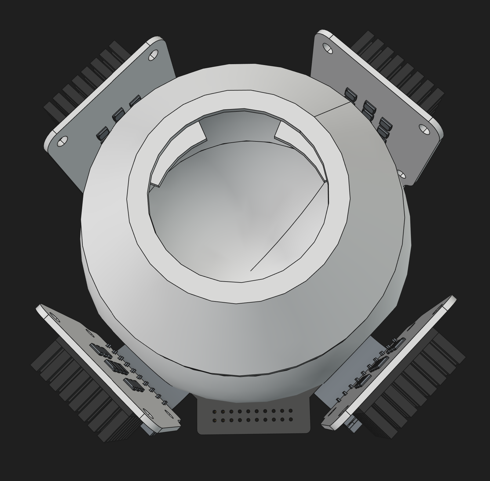
The four LED PCBs are evenly spaced around the equator of the sphere, mounted on an octagonal ring using alternating faces. The sphere is a 3D-printed assembly — three parts for the inner sphere in matte white PLA, four for the outer shell and rear mount in black PETG. Testing confirmed that matte white PLA performs comparably to a barium sulfate coating for this application — accessible materials, comparable quality.
Looking Forward
Tingopix already communicates with this DAC family over I2C, and the existing light chain uses the same components in a white-only configuration. Extending the software to select and combine spectral sources per capture channel is the natural next step.
Want to scan with white light? RGB? RGBW? Full multispectral? Each is a legitimate choice depending on the film, the workflow, and the time available. If one has the time but not the budget, this is a DIY option to make it possible.